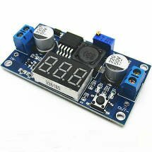
This is LM2596 2A Buck Step-down Power Converter Module DC 4.0~40 to 1.3-37V, it comes with a built-in voltmeter display and uses an advanced microcontroller.
This version of LM2596 DC-DC step-down (buck) power supply module includes the very useful addition of an integrated digital voltage meter. The voltage meter is capable of sensing both input and output supply voltages and can be quickly switchable between the two by pressing a voltage selection button on the module.
Together with its high precision multi-turn potentiometer, this means any desired output voltage within LM2596 supply range can be set without the need for an external voltage meter. The module also boasts a very high operating range with a DC input supply range of 4 – 35V and an adjustable output range of 1.3 – 35V.
In addition to LM2596’s voltage range, it has a high output current capability of up to 2A. Connection to the module is provided with the option of both input and output screw terminals or large solderable pads if a more permanent connection is required.
Output voltage calibration steps
Step 1: Adjust the right button so that “OUT” LED lighted, the voltmeter shows the value of output voltage; Press the right button for more than 2 seconds, release, voltmeter and “OUT” LED flashes in synchronization so that you enter the output voltage calibration mode.
Step 2: Press the right button (normal speed), the voltage value is adding up a unit; Press the left button, minus a unit; Due to a unit is less than 0.1V, the minimum voltage display to 0.1V, so you need to continuously press 1-5 times to see the voltmeter change 0.1V, how many times voltmeter change 0.1V by pressing the key, depending on the current display voltage, the higher the voltage, the fewer the number of press.
Step 3: Press the right button for more than 2 seconds, release, to exit the output voltage calibration mode. All parameters set to automatically power down to save.
Input voltage calibration steps
Step 1: Adjust the right button so that “IN” LED lighted, the voltmeter shows the value of input voltage; press the right button for more than 2 seconds, release, voltmeter and “IN” LED flashes in synchronization so that you enter the input voltage calibration mode.
Steps 2 and 3, consistent with the output voltage calibration method.
Notes: Maximum current is dependent on input and output voltages, ambient temperature and cooling. To achieve maximum ratings an external heatsink may be required. Maximum LM2596 operating temperature must not exceed 125oC otherwise permanent thermal damage can occur.
Features :
- Input reverse polarity protection
- Built-in output short protection function
- The built-in thermal shutdown function
- Press the right key to let the display show the input or output voltage. when the right “OUT” led light, it shows output, the left “IN” led show input.
- Power off memory function, show that road after power voltage values measured for the last time
- Press the touch button for 3 seconds to turn off LED display, touch the button again to turn on the LED display
- The band terminals, no iron can also be easy to use, and retention wire connection point


Reviews
There are no reviews yet.